


Water Stop Swimming Pool & Water Tank
Prinax Product
Water Stop Swimming Pool & Water Tank
Introduction
Loss Of Water By Leakage Is One Of The Primary Concerns Of Swimming Pool Owners, And It Is Particularly Important To
Provide Joints That Will Retain Water Under A Head. Besides Retaining Wa- Ter, Some Joints Must Also Accom- Modate At Least Some Movement In The Concrete. Often It Is Necessary To Transfer Load Across The Joint.
The General Approach To Locating Joints And Sealing Them Includes De- Signing To Minimize Movement At Any One Location And Providing Pos- Itive Methods Of Sealing. These Methods Utilize Waterstops Cast In TheConcrete And Sealants Located On The Water Side So That The Head Of Water Tends To Force Them Into The Joint Instead Of Out Of It.
Kinds Of Joints
The Kinds Of Joints That Are Useful In Pools May Be Classified In The Fol- Lowing Groupings:
1. Rigid Joints. These Are Com- Monly Called Construction Joints, Joints Between Segments Cast At Dif- Ferent Times Hut Purposely Joined Monolithically. These Joints Are In- Troduced Into The Structure Wherev- Er Work Must Be Suspended Tem- Porarily. It Is Intended That Movement Should Not Occur At These Places And That The Structure Behave Monolithically, As Though No Joint Had Ever Been Formed. Steel Can Be Continued Across The Joint.
2. Nonrigid Joints. There Are Three Types:
(A) Expansion Joints (Full Move- Ment Joints) Allow The Struc-
Ture To Move To A Limited Ex- Tent In Any Direction At That Location. They Not Only Ac- Commodate Movements Caused By Moisture Changes Or Thermal Changes But To Some Extent Relieve Stresses From The Differential Move- Ments Caused By Unstable Soil Conditions.
(B) Contraction Joints (Partial Movement Joints) Allow Movement Caused By Mois- Ture And Temperature Changes. Much Of This Move- Ment Occurs During The Early Life Of The Concrete From Dry- Ing Shrinkage And Cooling.
(C) Stress Relief Joints (Also Partial Movement Joints) Allow Movement From Moisture Or Temperature Changes But To A Lesser Degree Than Contraction Joints. They Are Primarily Meant To Accommodate Con Traction During The Very Early Life Of The Structure Especially Where Restraint May Be Im- Posed By Formwork. They Re- Semble Contraction Joints Ex- Cept That In Stress Relief Joints The Movement Is Intentionally Limited Further By Carrying Every Second Or Third Rein- Forcing Bar Across The Joint.
Joint Type And Location
Choosing The Type And Number Of Joints And Their Location Requires Consideration Of The Shape And Size Of The Pool And The Kind Of Service It Must Render. A Large Outdoor Swim- Ming Pool That Is Filled With Warm Water In The Summer But Left Empty All Winter Will Be Subject To Large Po- Tential Movements Or Stresses. AnIndoor Pool Kept At The Same Tem- Perature All Year Round And Emptied Only Once In Five Years Or More Will Undergo Little Stress Or Movement. The Outdoor Pool May Not Only Shrink And Expand From Tempera- Ture And Moisture Changes, But It May Move Differentially Because Of Unstable Ground. Such A Pool Must Either Be Built In A Number Of Inde- Pendent Sections With Expansion Joints For Full Movement Or Else Be Made Extremely Rigid, Possibly By Post-tensioning. In General It Is Best To Avoid Using Expansion Joints In The Structural Shell Whenever Possi- Ble. For Best Results There Usually Should Be No More Than 15 Feet Be- Tween Nonrigid Joints In Walls And Floors, Whether They Are Expansion, Contraction Or Stress Relief Joints.
Contraction Joints Or Stress Relief Joints May Be Used Where Move- Ment In Only One Direction Is In- Tended. The Steel Crossing Stress Re- Lief Joints Allows Less Movement In Them.
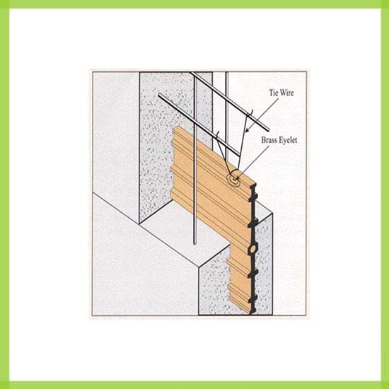
A Construction Joint Is Required When The First Several Inches Of Wall Are Cast Monolithically With The Floor (Figure 1). The Construction Joint Bonds This First Small Lift To The Remainder Of The Wall. Construction Joints Should Be Introduced At Any Other Place That Concreting Is Halt- Ed, As At The End Of The Day, But Whenever Possible Occasions Should Be Eliminated That Will Re- Quire Such Joints.
Crack Inducers May Sometimes Be Convenient To Insure The Correct Location Of Contraction Or Stress Re- Lief Joints. This Is Especially True When It Seems Necessary To Intro- Duce Stress Relief Joints To Divide A Wall Panel That Would Otherwise Be 20 Feet Or More In Length. Such A Panel Would Be Overly Long For Most Pools Unless Heavily Reinforced. The Crack Inducer Can Be An Inflatable Tube That Is Inserted Vertically From The Top Of The Wall To The Construc- Tion Joint In The Location Indicated In Figure 2.
The Tube Should Be Inflated To About One-quarter Of The Wall
Thickness. A 3⁄4-inch-wide And 3⁄4- Inch-deep Groove Should Be Provid-
Ed On The Water Side To Receive Joint Sealant, And If The Pool Is In Contact With The Ground A Similar Groove Should Be Made And Sealed On The Soil Side. The Tube Can Be Removed When The Formwork Is Removed. The Hole Should Immediately Be Plugged At The Top To Keep It Clean But It Should Be Sealed As Late In The Construction Process As Possible, Using An Expanding Or Nonshrinking Grout.
Joint Details
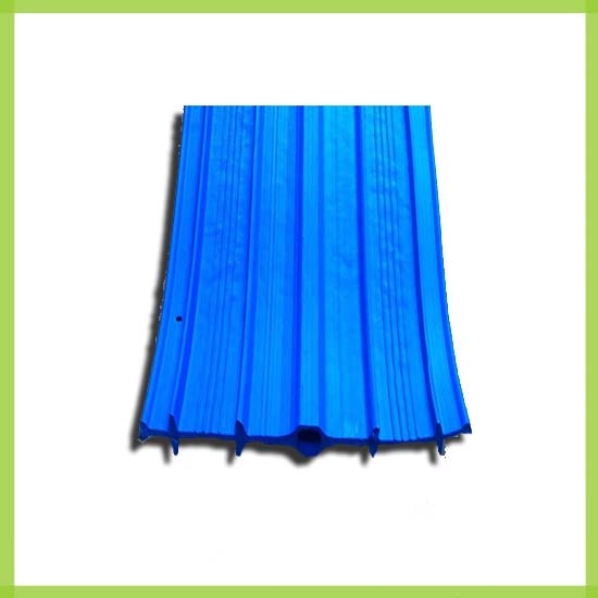
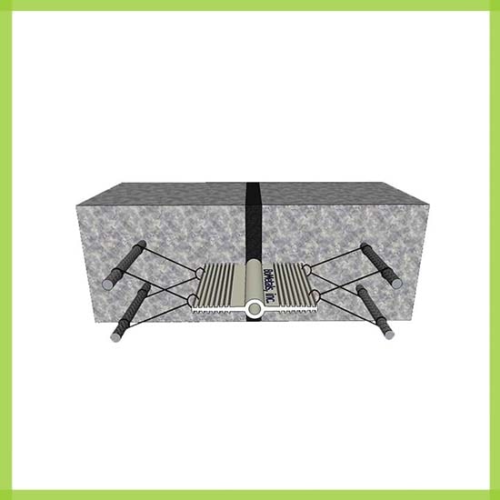
When Expansion Joints Are Used They Should Always Extend In A Con- Tinuous Line Across The Floor And Up The Walls. An Expansion Joint For A Floor Is Shown In Figure 3. The Joint, Which Should Be At Least 3⁄4 Inch Wide, Is Made By Forming At The Time Of Concreting. A Rubber Or Polyvinyl Chloride Waterstop Is Cast In The Base. The Floor Thickness Should Be Not Less Than 10 Inches So That The Waterstop Does Not Interfere With Compaction Of The Concrete. The Space Above The Waterstop Is Filled Nearly To The Top With A Filler That Is Long Lasting, Inert To Pool Chemicals And Elastic Enough To Maintain Con- Tact With The Joint Sides As The Joint Opens And Closes. The Filler Serves As A Mechanical Support For A Neo- Prene Compression Sealant Chosen From Among The Following:
Neoprene Compression Sealant Meeting Astm D2628-69;
Cold Applied Two-part Polysulfide Sealant Meeting U. S. Federal Speci- Fication Ss-s-00200c;
Hot Applied Bituminous Rubber Sealant Meeting U. S. Federal Speci- Fication Ss-s-164.
If A Bulk Sealant Is Used The Filler Must Be Brought To Within 3/4 Inch Of The Surface, But If A Neoprene Compression Sealant Is Used The Depth Of Opening Must Be Large Enough To Accept It.
Complete Bond Must Be Achieved Between Any Bulk Sealant And The Concrete. This Means That The Joint Must Be Dry And Clean Be- Fore Sealing.
An Expansion Joint In A Wall Is Shown In Figure 4. The Waterstop Is Cast At The Center Of The Wall. This
Joint Is Also 3/4 Inch Wide. Bulk Sealants May Be Used For Sealing At The Water Face In Place Of A Neo- Prene Compression Sealant. They Have The Same Space, Cleanliness And Dryness Requirements Here As When Used In Floors.
Contraction Joints In Floors Can Be Made As Shown In Figure 5 With A 10-inch-wide Waterstop At The Base. The Bond Between Adjacent Panels Is Broken By A Strip Of Plastic About 1/16 Inch Thick Or By Several Coats Of Bituminous Emulsion Painted Onto The Joint Face. Steel Mesh Is Not Car- Ried Across The Joint, And Tie Bars Are Not Used. The Groove Should Be 3⁄4 Inch Wide And 3⁄4 Inch Deep If Bulk Sealant Is Used, Or Possibly Deeper For A Neoprene Compression Sealant.
Many Engineers Think That Con- Traction Joints In Walls Should Al- Ways Line Up With Those In Floors, Al- Though Opinion Is Divided. Contraction Joints In Walls Can Be Made As In Figure 2 Or Figure 6. Pools Below Ground Must Have A Joint Groove On The Ground Side As Well As On The Water Side And Be Sealed On Both Sides.
Stress Relief Joints Are Made As In Figures 5 And 6, Including The Tie Bar In Figure 5, And With Every Second Or Third Steel Bar Crossing The Joint As In Figure 6.
When The Pool Shell Is Monolithic With The Building, Stress Relief Joints Should Be The Only Kind Used. Floor Slabs In Such Pools Should Have Joints That Cross The Full Width Of The Pool But That Are No More Than 50 Feet Long. There Should Be A Mini- Mum Of 6 Inches Of Well-compacted Concrete Above The Waterstop. The Walls Should Be At Least 12 Inches Thick And Rubber Waterstops (Not Polyvinyl Chloride Or Steel) Should Be Installed. Only The Highest Quali- Ty Sealants Should Be Used.
Construction Joints Must Be Made Monolithic And Rigid By Achieving A Strong Bond. In Floors The Form Should Be Removed Early— About 3 Hours After Completing Compaction Or Slightly Later In Cold Weather. The Vertical Face Should Then Be Sprayed With Water And Scrubbed With A Stiff Brush To Ex- Pose The Coarse Aggregate. If The Form Cannot Be Removed Until The Next Day The Surface Can Be Rough- Ened By Careful Hacking With A Ham- Mer And Chisel. If The Roughening Is Left To An Even Later Time A Bush- Hammer Can Be Used. But There Is Serious Danger Of Damage If Bush- Hammering Is Done Before The Con- Crete Is Seven Days Old.
Before Casting The Next Concrete The Joint Face Of The Previously Placed Concrete Should Be Well Brushed Or Blown Clean With Com- Pressed Air. A Better Bond Can Be As- Sured If A 1:1 Cement-sand Slurry Of A Creamy Consistency Is Brushed In Immediately Before Concreting. The Sand Should Pass The Number 8 Sieve. To Assure No Leakage It Is Ad- Visable To Provide A Groove In The Top (This Groove Is Later Sealed) And To Use A Waterstop In The Bottom In The Same Way As Shown In Figure 5.
Horizontal Construction Joints In Walls Can Be Prepared For Concreting By Brushing The Top Surface When The Concrete Is Only A Few Hours Old, Or Hacking It If It Is Older. The Surface Is Then Cleaned And Coated If Possi- Ble With A Grout Coat Scrubbed In Before Concreting. Vertical Joints Are Prepared In The Same Way. It Is Also Possible To Use A Retarder On The Form Of A Vertical Joint To Make It Easier To Scrub Away The Surface Mortar If More Than A Few Hours Are To Elapse Before Scrubbing. Since Careless Application Of A Retarder Can Cause Honeycombing In Adja- Cent Areas, This Method Should Be Used With Caution.
Waterstops Of The Kind Shown In Figure 4 Should Be Installed If The Wall Is Thick Enough (About 10 Inch- Es) To Permit Good Consolidation Around Them. Mild Steel Flats 1⁄8 Inch Thick And 6 Inches Wide May Also Be Used In Either Vertical Or Horizontal
Construction Joints In Walls.
A Horizontal Installation Using Polyvinyl Chloride Or Rubber Water- Stops Was Illustrated In Figure 1. The Waterstops Should Be Secured Tight- Ly To The Form At This Location To Pre- Vent Their Falling Over Or Getting Dis.